MRtrix3教程 #4 大脑组织边界
简介
我们几乎已经准备好开始我们的纤维束流线分析(streamline analysis),我们将在灰质和白质边界的随机位置放置种子(seeds)。一条流线将从每个种子生长出来,并从该种子区域追踪路径,直到它在另一个区域终止。一些流线会在一些没有意义的地方终止–例如,流线可能终止于脑室的边界。我们将剔除这些 “错误 “的流线,剩下的大部分流线似乎是连接遥远的灰质区域。
要做到这一点,我们首先需要在灰质和白质之间建立一个边界。MRtrix命令5ttgen(5tt就是表示生成了5种类型的组织,five-tissue-type)将使用FSL的FAST,连同其他命令,将解剖图像分割成五种组织类型(注意顺序):
- 灰质(Grey Matter, GM);
- 白质(White Matter, WM);
- 脑脊液(Cerebrospinal Fluid, CSF);
- 皮质下灰质(如杏仁核和基底神经节)(Subcortical Grey Matter,such as amygdala and basal ganglia);
- 病理组织(Pathological Tissue)。
一旦我们将大脑分割成这些组织类别,我们就可以使用边界作为掩码来限制我们放置种子的位置。
转换结构像数据
我们使用mrconvert命令将结构像转换为MRtrix格式。如果你在dwi目录下,你可以输入以下命令:
# 备注:..表示当前目录下的上一层目录
$ mrconvert ../anat/sub-CON02_ses-preop_T1w.nii.gz T1.mif
mrconvert: [100%] uncompressing image "sub-CON02_ses-preop_T1w.nii.gz"
mrconvert: [100%] copying from "sub-CON02_ses-preop_T1w.nii.gz" to "T1.mif"
之后,我们现在将使用命令5ttgen将解剖图像分割成上面列出的组织类型:
$ 5ttgen -h
MRtrix 3.0.4                         5ttgen

     5ttgen: part of the MRtrix3 package

SYNOPSIS

     Generate a 5TT image suitable for ACT

USAGE

     5ttgen algorithm [ options ] ...

        algorithm    Select the algorithm to be used to complete the script operation;
                     additional details and options become available once an
                     algorithm is nominated. Options are: freesurfer, fsl, gif,
                     hsvs

DESCRIPTION

     5ttgen acts as a 'master' script for generating a five-tissue-type (5TT)
     segmented tissue image suitable for use in Anatomically-Constrained
     Tractography (ACT). A range of different algorithms are available for
     completing this task. When using this script, the name of the algorithm to
     be used must appear as the first argument on the command-line after
     ...

$ 5ttgen fsl -h
MRtrix 3.0.4                       5ttgen fsl

     5ttgen fsl: part of the MRtrix3 package

SYNOPSIS

     Use FSL commands to generate the 5TT image based on a T1-weighted image

USAGE

     5ttgen fsl [ options ] input output

        input        The input T1-weighted image

        output       The output 5TT image

Options specific to the 'fsl' algorithm

  -t2 <T2 image>
     Provide a T2-weighted image in addition to the default T1-weighted image;
     this will be used as a second input to FSL FAST

  -mask MASK
     Manually provide a brain mask, rather than deriving one in the script


$ 5ttgen fsl T1.mif 5tt_nocoreg.mif
5ttgen:
5ttgen: Note that this script makes use of commands / algorithms that have relevant articles for citation; INCLUDING FROM EXTERNAL SOFTWARE PACKAGES. Please consult the help page (-help option) for more information.
5ttgen:
5ttgen: Generated scratch directory: /Volumes/Touch/Datasets/DTI/ds001226-download/sub-CON02/ses-preop/anat/5ttgen-tmp-OOBLVX/
Command:  mrconvert /Volumes/Touch/Datasets/DTI/ds001226-download/sub-CON02/ses-preop/anat/T1.mif /Volumes/Touch/Datasets/DTI/ds001226-download/sub-CON02/ses-preop/anat/5ttgen-tmp-OOBLVX/input.mif
5ttgen: Changing to scratch directory (/Volumes/Touch/Datasets/DTI/ds001226-download/sub-CON02/ses-preop/anat/5ttgen-tmp-OOBLVX/)
Command:  mrconvert input.mif T1.nii -strides -1,+2,+3
Command:  maskfilter /Applications/fsl/data/standard/MNI152_T1_1mm_brain_mask_dil.nii.gz dilate mni_mask.nii -npass 4
Command:  standard_space_roi T1.nii T1_preBET.nii.gz -maskMASK mni_mask.nii -roiFOV
Command:  bet T1_preBET.nii.gz T1_BET.nii.gz -f 0.15 -R
Command:  fast T1_BET.nii.gz
Command:  run_first_all -m none -s L_Accu,R_Accu,L_Caud,R_Caud,L_Pall,R_Pall,L_Puta,R_Puta,L_Thal,R_Thal -i T1.nii -o first
5ttgen: [100%] Generating partial volume images for SGM structures
Command:  mrmath [mesh2voxel_*.mif (10 items)] sum - | mrcalc - 1.0 -min all_sgms.mif
Command:  mrthreshold T1_BET_pve_2.nii.gz - -abs 0.001 | maskfilter - connect - -connectivity | mrcalc 1 - 1 -gt -sub remove_unconnected_wm_mask.mif -datatype bit
Command:  mrcalc T1_BET_pve_0.nii.gz remove_unconnected_wm_mask.mif -mult csf.mif
Command:  mrcalc 1.0 csf.mif -sub all_sgms.mif -min sgm.mif
Command:  mrcalc 1.0 csf.mif sgm.mif -add -sub T1_BET_pve_1.nii.gz T1_BET_pve_2.nii.gz -add -div multiplier.mif
Command:  mrcalc multiplier.mif -finite multiplier.mif 0.0 -if multiplier_noNAN.mif
Command:  mrcalc T1_BET_pve_1.nii.gz multiplier_noNAN.mif -mult remove_unconnected_wm_mask.mif -mult cgm.mif
Command:  mrcalc T1_BET_pve_2.nii.gz multiplier_noNAN.mif -mult remove_unconnected_wm_mask.mif -mult wm.mif
Command:  mrcalc 0 wm.mif -min path.mif
Command:  mrcat cgm.mif sgm.mif wm.mif csf.mif path.mif - -axis 3 | mrconvert - combined_precrop.mif -strides +2,+3,+4,+1
Command:  mrmath combined_precrop.mif sum - -axis 3 | mrthreshold - - -abs 0.5 | mrgrid combined_precrop.mif crop result.mif -mask -
Command:  mrconvert result.mif /Volumes/Touch/Datasets/DTI/ds001226-download/sub-CON02/ses-preop/anat/5tt_nocoreg.mif
Command:  5ttcheck result.mif
5ttgen: Changing back to original directory (/Volumes/Touch/Datasets/DTI/ds001226-download/sub-CON02/ses-preop/anat)
5ttgen: Deleting scratch directory (/Volumes/Touch/Datasets/DTI/ds001226-download/sub-CON02/ses-preop/anat/5ttgen-tmp-OOBLVX/)
这个命令将需要大约10-15分钟(性能好的电脑,不到5分钟就可以完成)。如果分割成功完成,当你输入mrview 5tt_nocoreg.mif时,你应该看到以下图像(按左右方向键可滚动浏览不同的组织类型):
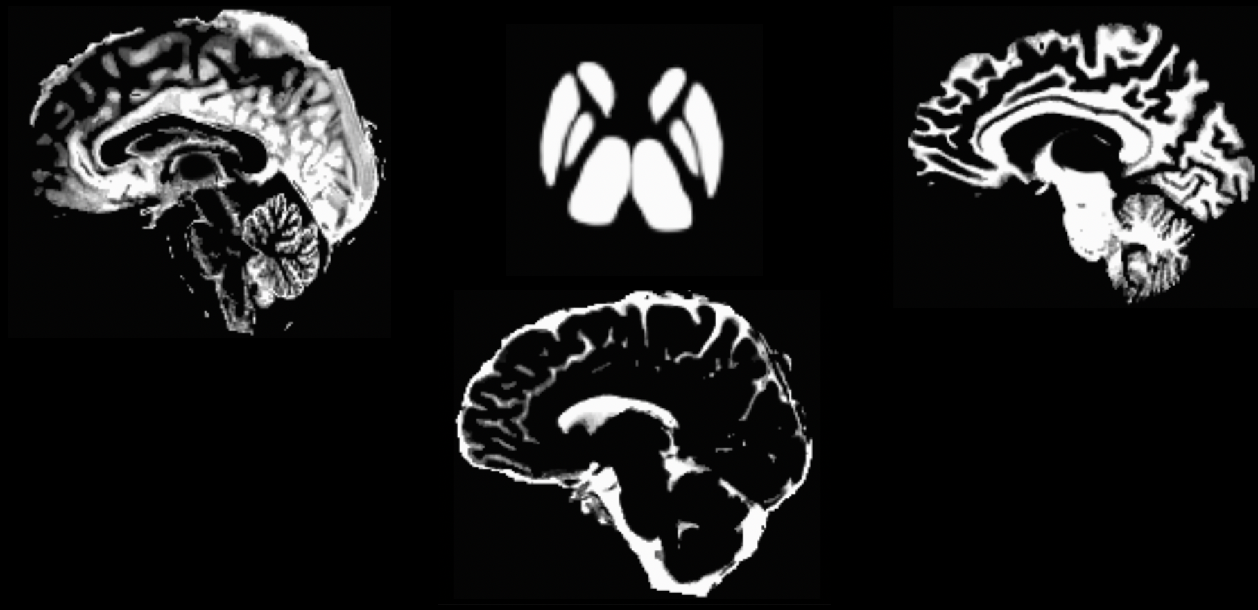
如果分割步骤失败,这可能是由于组织类型之间的对比度不够;例如,一些解剖图像的灰质和白质都很暗,或者两种组织类型都很亮。我们可以用AFNI的3dUnifize等命令增加组织间的强度对比(也称为强度归一化),来帮助分割过程,例如: \$ 3dUnifize -input anat.nii -prefix anat_unifize.nii,前后图像之间的差异可能很细微,但可以防止抛出分割错误。
配准扩散图像和解剖图像
如果分割已经完成,没有任何错误,我们的下一步是将解剖学图像(T1结构像)和扩散加权图像(DWI)进行配准。这可以确保组织类型的边界与扩散加权图像的边界相一致。因为即使两个扫描的位置有微小的差异,也都会影响到纤维束成像的结果。
我们将首先使用命令dwiextract和mrmath将扩散数据中的B0图像平均化。这些图像看起来最像T2加权的功能扫描,因为在采集过程中没有应用扩散梯度–换句话说,它们是在B值为0时采集的。要看这是如何工作的,请回到dwi目录,输入以下命令:
# 使用dwiextract首先提取出Bvalue为0的多个volumes,然后再使用mrmath函数在时间轴上对bvalue为0的数据进行平均。(即对提取出来的多个volumes平均)
$ dwiextract sub-02_den_preproc_unbiased.mif - -bzero | mrmath - mean mean_b0.mif -axis 3
dwiextract: [100%] extracting volumes
mrmath: [100%] preloading data for "/var/folders/39/93zn2fy95cd9b_b38zvmvgjc0000gn/T/mrtrix-tmp-CDi8x9.mif"
mrmath: [100%] computing mean along axis 3...
为了在扩散图像和解剖图像之间进行配准,因为MRtrix软件包的库中没有配准命令,所以我们需要使用另一个软件包FSL的命令flirt。(同理,其实我们也可以使用ANTs包中的配准算法)
# 第一步是将分割后的解剖图像和我们刚刚提取的B0图像进行转换
# 移动5tt_nocoreg.mif到当前的dwi目录下
mv ../anat/5tt_nocoreg.mif .

# mif转换为nifti
mrconvert mean_b0.mif mean_b0.nii.gz
mrconvert 5tt_nocoreg.mif 5tt_nocoreg.nii.gz

# [fslroi](https://fsl.fmrib.ox.ac.uk/fsl/fslwiki/Fslutils)
# 由于 flirt 只能处理单个 3D 图像(不是 4D 数据集),我们将使用 fslroi 提取分割数据集的第一个Volume,这对应于灰质。
# fslroi <input> <output> <tmin> <tsize> # 同理,我们可以从在时间维度上抽取出WM、CSF等组织类型,形成单个Volume
# fslroi 5tt_nocoreg.nii.gz 5tt_vol1.nii.gz 1 1  # WM
# fslroi 5tt_nocoreg.nii.gz 5tt_vol2.nii.gz 2 1  # CSF
fslroi 5tt_nocoreg.nii.gz 5tt_vol0.nii.gz 0 1  # GM

# 然后我们使用flirt命令来配准这两个数据:
# 注意,查看flirt的帮助文档为flirt -help
# 该命令使用灰质分割图(即 "5tt_vol0.nii.gz")作为参考图像,也就是说,它保持静止状态。然后移动平均的B0图像,以找到与灰质分割的最佳匹配。这个命令的输出,"diff2struct_fsl.mat",包含了用于在灰质分割上叠加扩散图像的变换矩阵。
flirt -in mean_b0.nii.gz -ref 5tt_vol0.nii.gz -interp nearestneighbour -dof 6 -omat diff2struct_fsl.mat

# 现在我们已经生成了我们的变换矩阵,我们将需要把它转换成可以被MRtrix读取的格式。也就是说,我们现在已经准备好在短暂离开MRtrix之后回到MRtrix中。transformconvert命令可以做到这一点:
transformconvert diff2struct_fsl.mat mean_b0.nii.gz 5tt_nocoreg.nii.gz flirt_import diff2struct_mrtrix.txt

# 请注意,上述步骤使用了解剖学分割图作为参考图像。我们这样做是因为通常情况下,如果参考图像具有更高的空间分辨率和更清晰的组织类型区分,那么配准会更准确。然而,我们也希望在预处理过程中尽可能少地引入对功能数据的编辑和插值。因此,既然我们已经有了将弥散图像转化为解剖图像的步骤,我们就可以采取转化矩阵的逆运算来做相反的事情--即将解剖图像配准到弥散图像:
mrtransform 5tt_nocoreg.mif -linear diff2struct_mrtrix.txt -inverse 5tt_coreg.mif
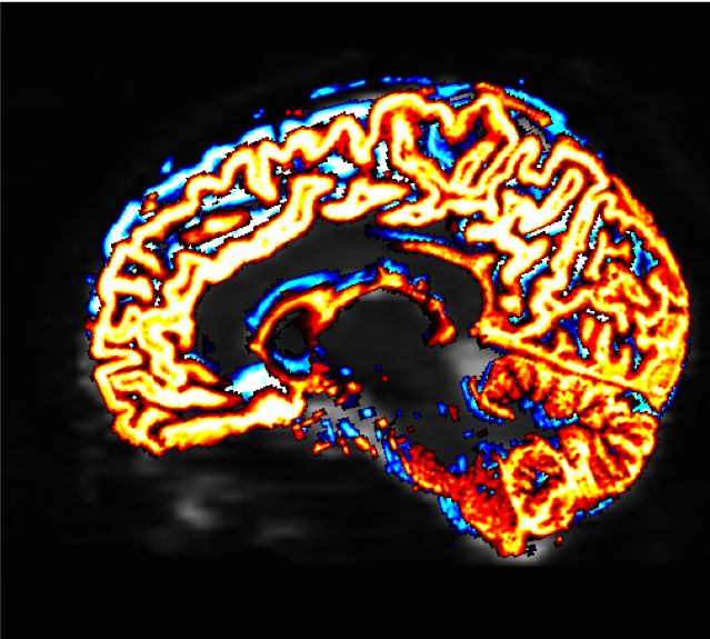
生成的文件“5tt_coreg.mif”可以加载到 mrview 中以检查配准的质量
mrview sub-02_den_preproc_unbiased.mif -overlay.load 5tt_nocoreg.mif -overlay.colourmap 2 -overlay.load 5tt_coreg.mif -overlay.colourmap 1
“overlay.colormap"选项为每张被加载的图像指定不同的颜色代码。在这种情况下,配准前的边界将被描述为蓝色,配准后的边界将被显示为红色。
创建 “种子"边界的最后一步–分离灰质和白质的边界,我们将用它来创建流线的种子–是用5tt2gmwmi(代表 “5组织类型(分割)到灰质/白质界面”)命令创建的。
$ 5tt2gmwmi -h
MRtrix 3.0.4                        5tt2gmwmi                        Dec 14 2022

     5tt2gmwmi: part of the MRtrix3 package

SYNOPSIS

     Generate a mask image appropriate for seeding streamlines on the grey
     matter-white matter interface

USAGE

     5tt2gmwmi [ options ] 5tt_in mask_out

        5tt_in       the input 5TT segmented anatomical image

        mask_out     the output mask image


OPTIONS

  -mask_in image
     Filter an input mask image according to those voxels that lie upon the
     grey matter - white matter boundary. If no input mask is provided, the
     output will be a whole-brain mask image calculated using the anatomical
     image only.
     ...

$ 5tt2gmwmi 5tt_coreg.mif gmwmSeed_coreg.mif
5tt2gmwmi: [100%] Generating GMWMI seed mask
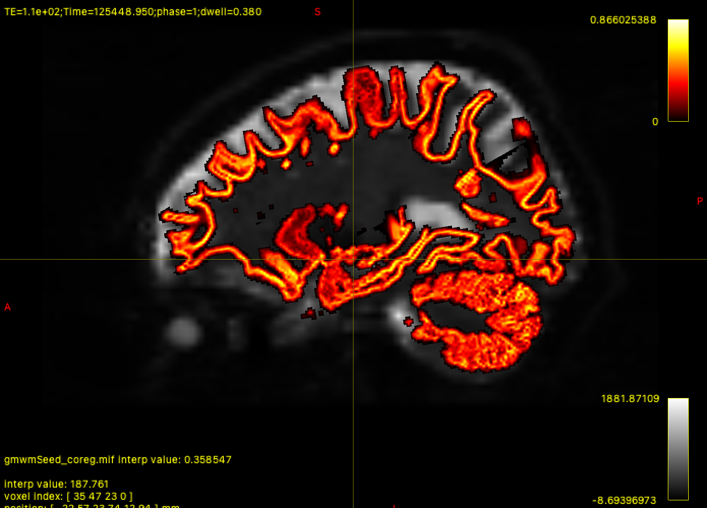
同样,我们将使用mrview检查结果,以确Interface在我们认为应该的位置
mrview sub-02_den_preproc_unbiased.mif -overlay.load gmwmSeed_coreg.mif